Welcome to the fourth and final post in this series. Sorry for those that have been following for the long delay, I’ve decided to make some career changes that have kept me busy. In this post, I’ll try to tie everything together, but I also leave some final decisions on solutions chosen based on your own business requirements. If you haven’t yet followed along, please see my prior three posts Private Cloud Architecture – pt 1, Private Cloud Architecture – pt2 – Selecting Providers, and Private Cloud Architecture – pt3 – Hardware.
General Architecture
The below diagram will provide a general overview of the proposed architecture for the private cloud. Keep in mind there are some things not visualized in this diagram such as the switches and optical line protection equipment.
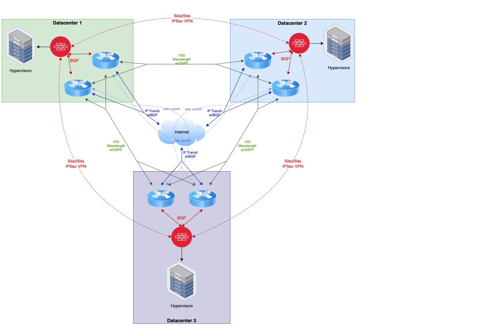
As you can see from the visualization, there are a lot of paths for traffic to flow. The goal is to eliminate any single point of failure per datacenter, while also being able to quickly reroute in the event of an upstream outage from one or more providers. It may appear in the diagram that there is only a single firewall, but actually represents a firewall cluster. Firewall devices need proprietary state/session sharing, so more than one firewall unit can not load balance or fail over independently like you can with a router that uses standardized routing protocols.
Another thing you might take note of above is the GRE tunnels; this is an optional component. The GRE tunnels are used as a poor-man’s backup P2P circuit which is de-prioritized so it only has traffic flow if both physical P2P Circuits at one datacenter are out. This will prevent a datacenter being completely isolated during a multiple-carrier outage event, but if your traffic load cannot handle higher latency or jitter, then by all means don’t use it (however you might want to measure this before making such a decision).
In this build-out I am assuming a 5yr hardware life for all equipment, and will use that as a basis for all pricing information provided below. This also makes it easy to amortize the cost over the period of time for price comparison with public cloud options.
Routing Architecture for the Private Cloud
In the private cloud architecture, the routers exist solely in the public network (e.g. Internet) for exchanging public routes, either with upstream providers, with each other, or to the firewalls protecting the services offered by the private cloud. The firewalls are used to protect private networks from the public internet and only allow designated traffic inbound and out.
Each router will have multiple small subnets for communicating with other routers, whether they are in the same datacenter or in a remote datacenter. OSPF is used as the IGP to exchange these subnets/routes so that every router can communicate with every other router within the architecture. Realistically though, using eBGP would be fine as well if you assign a private ASN per DC for these links, using OSPF in this limited case was just slightly easier.
The subnets that should be assigned from your own address pool (cut from your larger IP Registrar-assigned blocks), and participate in OSPF are:
- 3x IPv4/29 (IPv6/126) for each cross-dc P2P link, with 4 total routers in the subnet (2 per datacenter) assigned to the respective vlan interface.
- 3x IPv4/29 (IPv6/126) for each Link between the 2 routers in the datacenter to the firewall cluster in the same datacenter assigned to the respective vlan interface.
- 6x IPv4/32 (IPv6/128), one per router, for iBGP endpoints assigned on loopback interface.
- Optional. 12x IPv4/31 (IPv6/127) for GRE interfaces connecting each router in a remote datacenter to every other router in every other remote datacenter (but not to its peer router in the same datacenter).
You will also have additional IP subnets assigned from your upstream IP Transit providers for peering purposes. Come up with a meaningful IP addressing scheme that makes sense and is predictable (meaning based on the ip address alone, you can determine where it resides and maybe even what its purpose is). I like to assign a /24 to each datacenter out of a larger chunk. I prefer thinking in terms of left/right when I do addressing to decide which datacenter is considered the owner for point to point links, and that owner also takes the lower address in the subnet. My preference is the datacenter to the right is the owner. This way, the addressing translates logically from datacenter to datacenter as you go around the triangle. Keep all router configurations as identical as possible (with the exception of the ip addresses themselves). Always heavily document the addresses, preferably using a diagram to easily cross-reference during troubleshooting.
You will want to receive BGP full tables, but no default gateway, from each upstream IP Transit provider. For advertised routes out to transit providers, you will use an aggregate route that covers at least the micro subnets and are of minimum size IPv4/24 and IPv6/48. All routers in your architecture need to iBGP peer with each other (I assume you already know this, but never hurts to reiterate).
Next, you want to advertise via BGP only a generated default route to your firewalls, and accept routes you’ve pre-determined to be allowed to be advertised from your firewalls (some portion of the IP Registrar-assigned blocks). Typically you will use a private AS number to peer with your firewalls then ensure the private AS is rewritten before possibly advertising routes back out to the IP Transit providers.
Regarding the use of GRE tunnels, never use your own IP addresses unless you want a mess of routing loops. Use the IP Transit provider’s assigned IPs for peering for your GRE tunnels. Also assign a high OSPF metric so that traffic does not normally flow over this path even if one link is out, I typically use a metric of 25, but really 3 or higher would suffice (if using eBGP, use a lower local-preference for routes received).
Finally, always use aggressive BFD timers on OSPF and BGP connections (other than those traversing GRE tunnels) so you can quickly reroute (sub-second!) when there is a link failure. Also, always ensure you use best practices with route filtering and local firewall rules, and don’t accidentally accept a default route from IP Transit providers or accidentally advertise routes from other transit providers to each other. Always respect your MANRS.
Firewall Architecture for the Private Cloud
The firewall in this architecture will handle things such as site to site VPN tunnels using BGP to exchange routes across the VPN, NAT for private IPv4 space, BGP peering with your routers, basic intrusion detection and prevention, zone based firewall rules for ingress and egress, as well as providing network segmentation for various security levels within the private network.
At a minimum, the firewall should have 2 security zones, a public side and a private side, though typically there will be multiple private zones. Due to limited IPv4 address space, the private zone will use private IP addresses such as from 10.0.0.0/8, 192.168.0.0/16, or 172.16.0.0/12, and then use destination NAT to forward traffic from the public ip ranges. For IPv6, you won’t use NAT as there is plenty of address space, and using a zone based firewall will ensure you are filtering all inbound and outbound traffic.
Site to Site VPNs are used to exchange traffic from equivalent security zones within each datacenter, with routes being exchanged via BGP. You’d typically have a single IKEv2 session between each DC, then pop out a VNI with its own IPSec session into each security zone. I’d recommended treating this traffic the same as intra-dc traffic, meaning if you normally let machines on the same broadcast domain communicate with each other, it would make sense to allow machines in a different datacenter to exchange traffic with machines in the same security zone. As long as the same hardening and security policies are followed at each datacenter, this should not pose any additional security risk. It should also be mentioned that BFD should not be used across the VPN links, we are handling the underlying route failover at the core router level, not within the firewalls. If we did this at the firewall level, and routes started changing, you would break connections since firewalls are flow based not packet based.
When allowing traffic to traverse different zones, always use the most strict rule possible. It often does not make sense to allow one security zone to freely access another security zone; restrict to exact IPs and ports necessary. Also, a lot of network administrators forget about locking down egress to the public internet, most internal machines should not have public internet access. This does mean you need to provide some internal servers for things you might think you need internet access for, such as DNS, and NTP, Authentication and Authorization, and package update mirrors.
Finally, most firewalls will provide some sort of intrusion detection and prevention, up to at least OSI Layer 4. These should be enabled on public interfaces at a minimum, but also generally a good practice to enable on private interfaces at albeit a more permissive level (Juniper SRX calls this Screens, don’t confuse it with their other offerings). Next-Gen firewalls are currently all the rage that can handle deep packet inspection up to Layer 7, including things like SSL/TLS endpoint decryption …. I personally haven’t jumped on board with that … I think decrypting SSL/TLS traffic on your firewall might open up more security holes than it could potentially close (not to mention its not cheap).
Hypervisor Decisions
VM Storage
Ceph. Period. Full Stop. No seriously, don’t even consider anything else. Ceph is a distributed block storage software solution. It is highly resilient and performant. You can consider this a distributed SAN solution, where all your machines can participate as both clients and servers in the storage network, this is commonly referred to as a hyperconverged deployment.
In short, each hyperconverged hypervisor will run its own Ceph monitor and manager, as well as a Ceph OSD daemon per physical disk. The monitor and manager are what controls the ceph cluster, and each OSD is responsible for just the data residing on each disk. Ceph uses complex distribution algorithms called Crush Maps that can be customized to distribute data across data centers, cages, racks, and servers (however in our use case, we only care about distributing data redundantly across servers). Each datacenter will run its own independent Ceph cluster.
If using spinning rust (HDD) with an external JBOD enclosure, it is recommended to dedicate an NVMe disk per roughly each 10 spinners for blocks.db for significantly increased performance. Create an LVM partition dedicated to each spinner on the NVMe of 2-4% the size of the spinner, but not less than 40G. Remember, if the NVMe disk fails, all spinner OSDs associated with that NVMe will also fail.
Once the cluster is set up, you would then create a Pool which tells Ceph the desired redundancy level and even possibly the storage class (e.g. NVMe vs HDD) you want to use. I’d recommend creating one pool for fast access on NVMe (such as databases) using a replica of 3. Then a bulk data storage pool using an erasure coded pool on NVMe using k=3,m=2 (for every 3 data blocks generate 2 parity blocks) which gives the same redundancy as replica 3, but instead of the data storage requirements being 3x, it only requires 1.67x the space! The values used for k+m cannot exceed the total number of servers, hence the values chosen, but it is recommended k be a power of 2 greater than 2 if possible. If you have 10 (or more) nodes, k=8,m=2 would give you the same redundancy factor, but only require 1.25x the space, calculate via (k+m)/k. If also using spinning rust, create another erasure encoded pool for that.
You would then use these generated storage pools as the storage pools within your hypervisor and expose them based on the needs, each VM could have a virtual block device associated with one or more storage pools.
Finally, Ceph offers additional add-ons like CephFS, which can be considered a clustered NFS-like solution meant for storing files, which is perfect for storing things like ISO images for creation of VMs where the hypervisor might require them be stored as files rather than within a virtual block device. Then there’s also the Rados Gateway which provides AWS S3 API compatibility for object storage which can provide considerable additional value to VMs running within the environment. It can also be configured to automatically replicate to one or more datacenters providing additional elasticity.
Hypervisor Software
The recommended hypervisor itself is Linux KVM (vs alternatives like VMWare or Xen), however its unlikely you’ll actually interact with the hypervisor itself, but instead a set of management interfaces layered on top. By far the simplest to set up in this environment is Proxmox VE. It uses Linux KVM + QEMU running on Debian Linux under the hood, has great integration with Ceph, supports the most common features such as live migration between hypervisors, cloning, as well as VM high availability and snapshotting. It also has a rich ReST API and is introducing more and more SDN and orchestration features with each release.
I’ve used Proxmox VE for a large number of years, and it has proven to be rock solid at what it does, and is easy to administer and upgrade, however it really is best suited for smaller environments (e.g. no more than 16 nodes per cluster), and its multi-tenancy support could use a bit of work. They have both an open source and a commercial version. If you use Proxmox VE, I’d strongly suggest purchasing commercial licenses to help them further develop this great product.
If you are entertaining repatriating your infrastructure (e.g., away from AWS or Azure), have multi-tenancy needs, or are wanting to use “cloud-native” technologies (e.g. using something like Terraform / Infrastructure as Code), then Proxmox VE may not be the best fit. When using Proxmox VE, the entire networking stack is controlled by the network administrators, including all firewall rules, there is no self-service capability by those with hypervisor access (though that may change in the future as they enhance SDN capabilities). This is fine if the same team that is deploying systems is also managing the network, but may be cumbersome for larger teams with more granular duties.
For a more cloud-native approach the recommended solution would be Apache CloudStack. In the last few years it has come a long way and is the easiest (and probably the best) private cloud platform out there, without the complexities of OpenStack (yes, CloudStack is arguably less flexible, but in ways that realistically don’t matter). CloudStack has great native support for Ceph, is designed from the ground-up for multi-tenancy, and Terraform has full-featured support. Since it supports full SDN capabilities, it allows users to creates virtual routers, load balancers, and private networks themselves with the access rules they require. It is used by many of the smaller public cloud providers, as well as by large enterprises for their private clouds.
Except for specific cloud-provider lock-in technologies (e.g. AWS Aurora DB, AWS Lamdas), CloudStack provides the entire feature-set of public cloud offerings, and is completely open-source and free.
I’d strongly recommend watching this video by Wido on what I would consider the ultimate architecture with CloudStack (which neatly fits into the architecture I have described so far, with the addition of VXLAN support for scalability).
Conclusion
At this point, you should have a good idea of all the costs amortized to a monthly basis. The one thing I haven’t yet added in is the personnel costs. In my first post I mentioned you should already have this staff with the institutional knowledge necessary to deploy the cloud, but of course that doesn’t make for a fair comparison with public cloud costs.
Once the private cloud is deployed, maintenance on the cloud infrastructure itself should be fairly minimal, measured in only a few hours per month on tasks like patching, upgrades, and hardware maintenance. A vast majority of the time spent by IT staff will be on things external to the private cloud and would be largely similar to the staffing requirements of deploying on a public cloud.
That said, this kind of deployment still relies on minimum staffing levels, even if a vast majority of the their time isn’t spent on private cloud-specific activities. Again, I repeat, these personnel are not dedicated to running the private cloud, they will have other similar duties to what they would have if running on a public cloud but I am including their entire cost in the provided numbers even if only 20% of their time even goes into maintaining anything specific to the private cloud. I would recommend two senior IT personnel (~$140k/yr) and one junior IT (~$80k/yr), which when using a 1.4x multiplier for employee overhead (benefits, equipment, HR) that comes out to $42k/mo.
So now we can come up with a more complete monthly amortized cost by adding together our various components: $10k (providers), $11.5k (hardware), $42k (personnel) which comes to a grand total of $63.5k/mo. Now, compare that to your AWS or Azure bill.
So what does this tell us? People are what cost the most, trying to cut corners on hardware and service providers will not prove to be worthwhile, instead focus on getting the best talent you can find (and afford). And remember, those staffing levels will be able to handle much more than basic maintenance of the private cloud, they should also be deploying and maintaining services that utilize the cloud they have built.